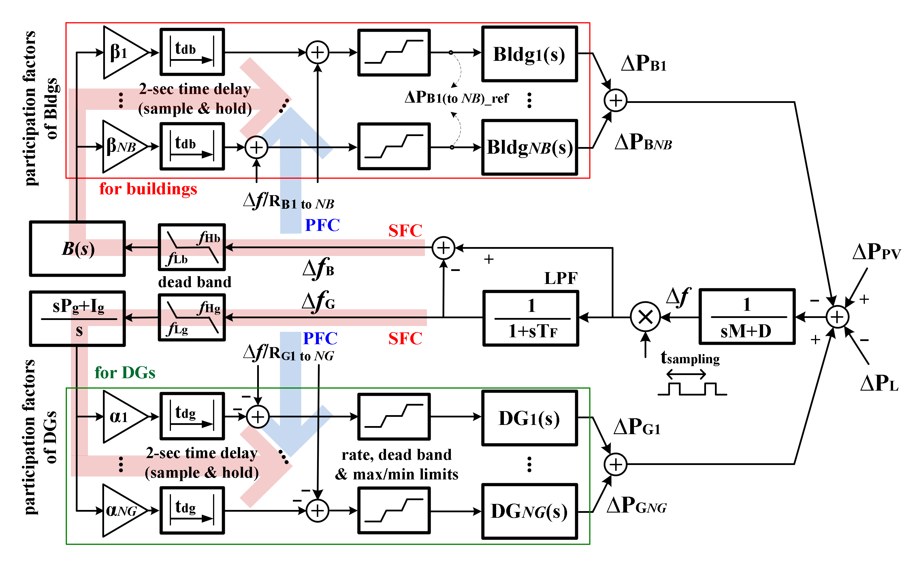
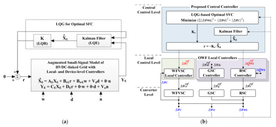
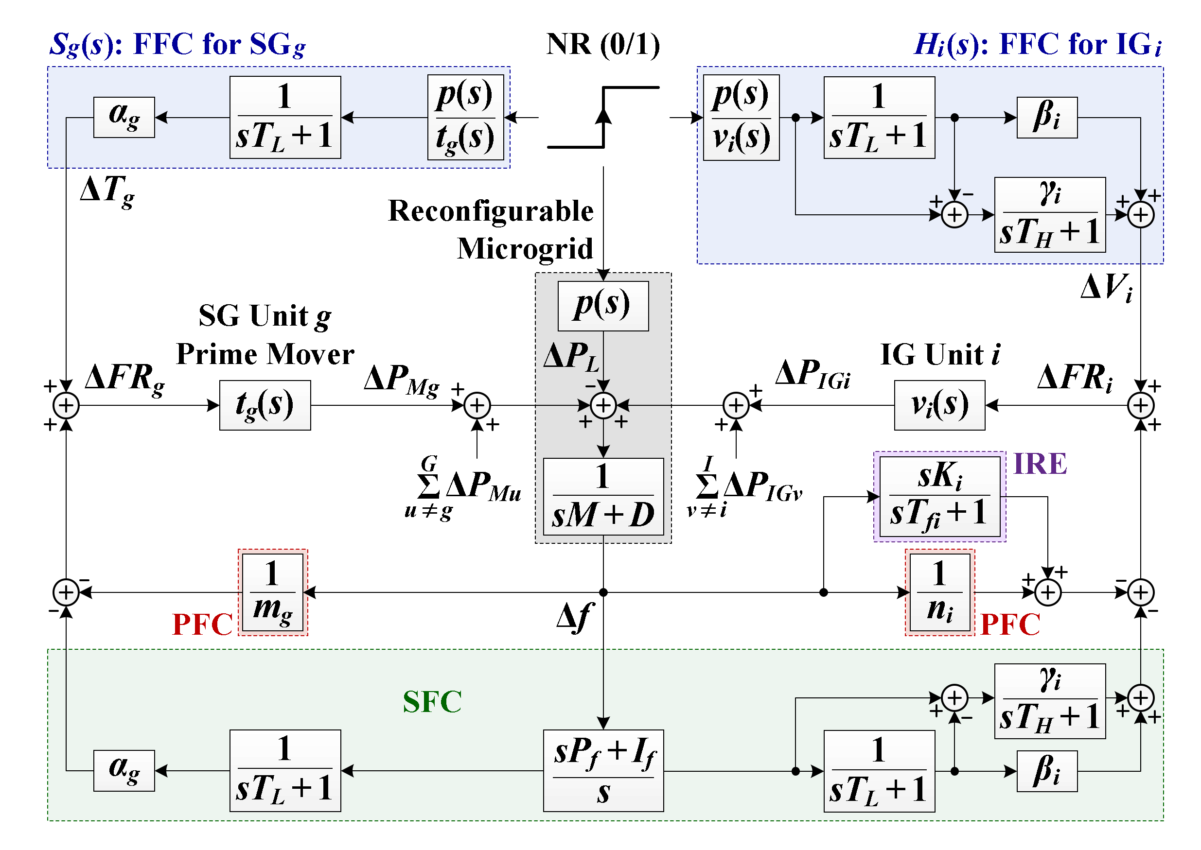
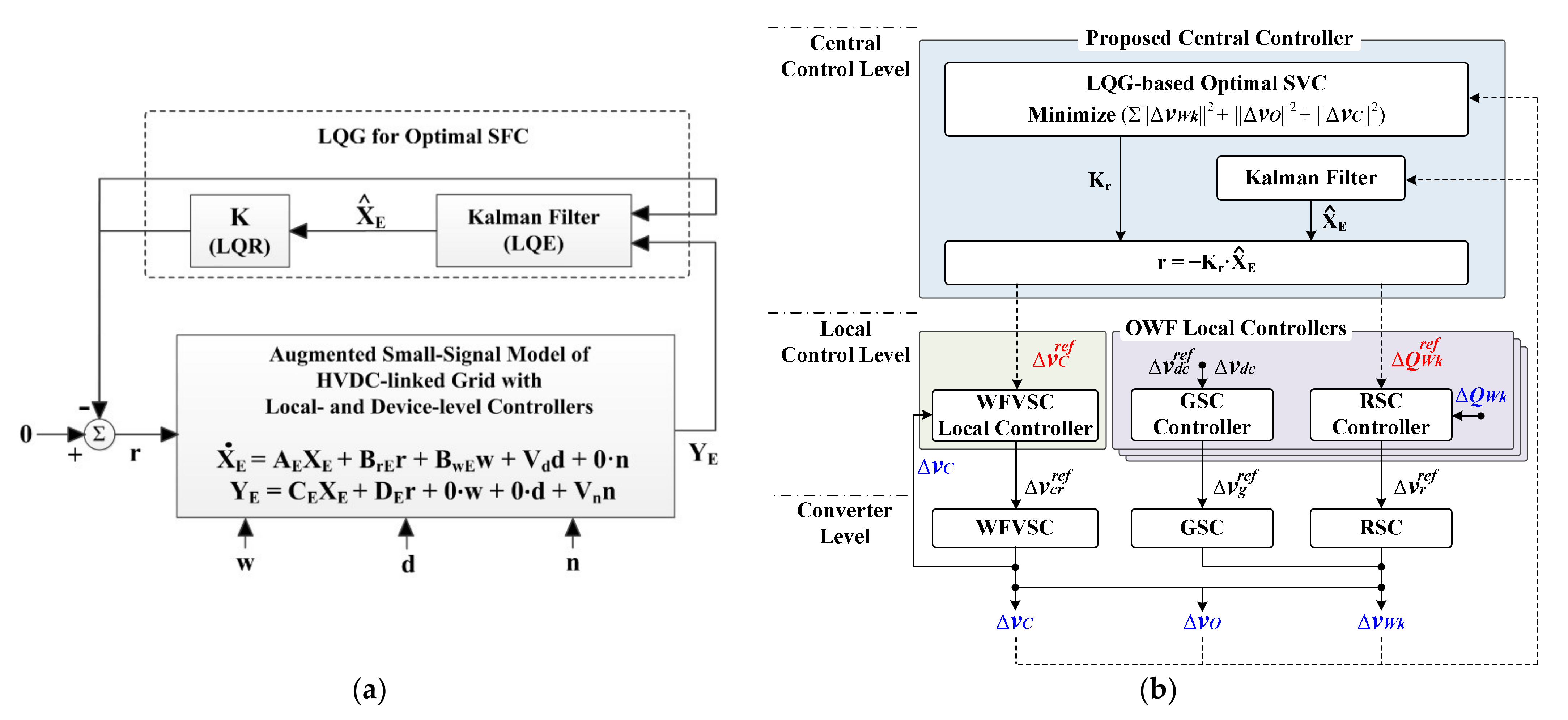
10+ hvdc block diagram
11 Sketch a functional block diagram of a bi-polar HVDC scheme. HVDC Transmission Control and Protection TI Solutions14 List of Tables Table 1-1.

Electrode Line Wikiwand
The converter models rectifier and inverter DC transmission system phase lock oscillators.

. The output voltage can be calculated as follows. The converter models rectifier and inverter DC transmission system phase lock oscillators. Block Diagram of HVDC Transmission System The block diagram of hvdc transmission system is shown in Figure.
VoutVin tontoffVin or VoutVin tontoff1 Circuit and working Circuit diagram of the boost converter using. HVDC TRANSMISSION LINE BLOCK DIAGRAM AND WORKING. The control block diagram model of HVDC system simplifies in understanding and modelling the complex operation of the HVDC system.
Figure 310 HVDC power transmission system. Figure 311 B-H curve with hysteresis characteristics and a DC biased condition. Main components of HVDC system are as under.
Structure for VSC-HVDC transmission suitable for stability studies such as studies of voltage angle and frequency stability phenomena of combined ac and dc systems. In the block diagram G F represents the measuring filter time constant for the DC current. The schematic diagram of a two-terminal system is presented in Fig.
Desired features of an LCC-HVDC control system are 10-11. Limit maximum dc current using constant-current control in the rectifier to protect the converter valves. A linearized model of an HVDC system is presented in a control block diagram form.
A linearized model of an HVDC system is presented in a control block diagram form. HVDC Control and Protection System Block Diagram13 Figure 5-1. A DC-biased hysteresis loop.
A high-voltage direct current HVDC electric power transmission system also called a power superhighway or an electrical superhighway uses direct current DC for electric power. 3 12 The harmonic content of a twelve-pulse converter phase current is given by 2205I Lsinωt02I Lsin11ωt017I. Karawita and Annakkage adopt the state-space modeling method and establish a model for LCC-HVDC system in a control block-diagram form which can simplify.
General Block Diagram The configuration shown in figure 1 mainly consists of ac filters transformer converters phase reactors dc filters circuit breakers and capacitors. The model can be used in small signal.

Hvdc Converter Wikiwand

High Voltage Direct Current Wikiwand
What S The Best Book To Learn Hvdc Quora

Hvdc Converter Wikiwand

High Voltage Direct Current Wikiwand

Electrical Grid Wikiwand

Electrode Line Wikiwand

Applied Sciences Free Full Text Research Needs For Realization Of Zero Carbon Power Grids With Selected Case Studies Html

Electrode Line Wikiwand

Power Electronics Wikiwand

Magnox Wikiwand

High Voltage Direct Current Wikiwand

Applied Sciences Free Full Text Research Needs For Realization Of Zero Carbon Power Grids With Selected Case Studies Html

Applied Sciences Free Full Text Research Needs For Realization Of Zero Carbon Power Grids With Selected Case Studies Html
2

Applied Sciences Free Full Text Research Needs For Realization Of Zero Carbon Power Grids With Selected Case Studies Html

Hvdc Converter Wikiwand